1. Gabatarwa
Thank you for choosing the Voltcraft VC-11 Digital Multimeter. This portable, Category III, 250V multimeter with a 2000-count display is designed for accurate electrical measurements in various applications. This manual provides essential information for safe operation, proper use, and maintenance of your device. Please read it thoroughly before use and keep it for future reference.
2. Bayanin Tsaro
WARNING: Electrical shock hazard. Improper use of this meter can cause damage, shock, injury, or death. Read and understand this manual before operating the meter.
- Always ensure the meter is in good working condition and the test leads are not damaged.
- Kar a yi amfani da fiye da ƙididdigan voltage, as marked on the meter, between terminals or between any terminal and ground.
- Yi amfani da taka tsantsan lokacin aiki da voltages above 25V AC RMS or 35V DC. These voltagyana haifar da haɗari.
- Koyaushe cire haɗin jagoran gwajin daga da'ira kafin canza ayyuka ko jeri.
- Do not operate the meter with the battery cover removed or loosened.
- Adhere to local and national safety codes. Use personal protective equipment (PPE) such as approved safety glasses and electrically insulated gloves.
3. Samfurin Ya Ƙareview
The Voltcraft VC-11 is a compact digital multimeter featuring a clear LCD display, a rotary function switch, and input jacks for test leads. It is designed for measuring DC/AC voltage, DC current, resistance, and includes diode and continuity test functions.
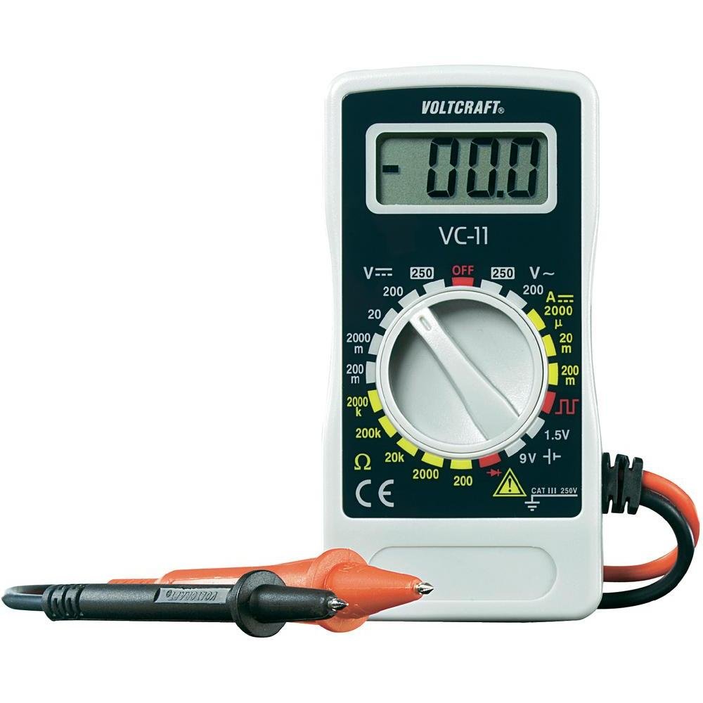
Hoto 1: Gaba view of the Voltcraft VC-11 Digital Multimeter with test leads connected. This image shows the LCD display, rotary switch, and input terminals.

Hoto 2: Angled view of the Voltcraft VC-11 Digital Multimeter, highlighting the compact design and the CE marking.

Figure 3: The Voltcraft VC-11 Digital Multimeter shown with its test leads detached, illustrating the input ports.
3.1 Abubuwan
- Nuni LCD: Yana nuna karatun ma'auni, raka'a, da alamun aiki.
- Juya Juya: Ana amfani da shi don zaɓar ayyukan auna da jeri.
- Shigar Jacks: Ports for connecting the test leads (COM, VΩmA).
- Jagoran Gwaji: Red and black leads for connecting to the circuit under test.
4. Saita
4.1 Shigar da Baturi
The Voltcraft VC-11 requires a 9V battery for operation (not included). To install or replace the battery:
- Ensure the multimeter is turned OFF and disconnect all test leads.
- Nemo murfin sashin baturi a bayan mita.
- Yi amfani da sukudireba don cire sukurin da ke ɗaure murfin batirin.
- Cire murfin a hankali.
- Connect a new 9V battery to the battery clip, observing correct polarity.
- Sanya batirin a cikin ɗakin sannan a maye gurbin murfin, a ɗaure shi da sukurori.
4.2 Haɗa Jagoran Gwajin
Always connect the black test lead to the 'COM' (common) jack. Connect the red test lead to the appropriate input jack based on the desired measurement:
- Don Voltage (V), Resistance (Ω), Diode, and Continuity measurements, connect the red lead to the 'VΩmA' jack.
- For Current (A) measurements, connect the red lead to the 'VΩmA' jack (for mA range).
5. Umarnin Aiki
Kafin ɗaukar wani ma'auni, tabbatar da cewa an haɗa jagororin gwaji daidai kuma an saita maɓallin juyawa zuwa aikin da ake so da kewayon da ake so.
5.1 Aunawa DC Voltage (V=)
- Saita maɓallin juyawa zuwa DC Vol da ake sotage (V=) range (e.g., 200mV, 2V, 20V, 200V, 250V). If the voltage ba a san shi ba, fara da mafi girman kewayon kuma rage shi kamar yadda ake buƙata.
- Connect the black test lead to the 'COM' jack and the red test lead to the 'VΩmA' jack.
- Connect the test probes in parallel across the component or circuit to be measured.
- Karanta juzu'intage darajar a kan LCD nuni.
5.2 Aunawa AC Voltage (V~)
- Saita maɓallin juyawa zuwa Vol ɗin AC da ake sotage (V~) range (e.g., 200V, 250V).
- Connect the black test lead to the 'COM' jack and the red test lead to the 'VΩmA' jack.
- Connect the test probes in parallel across the AC source or component.
- Karanta juzu'intage darajar a kan LCD nuni.
5.3 Measuring DC Current (A=)
- Set the rotary switch to the desired DC Current (A=) range (e.g., 2000µA, 20mA, 200mA).
- Connect the black test lead to the 'COM' jack and the red test lead to the 'VΩmA' jack.
- GARGADI: To measure current, the meter must be connected in series with the circuit. Break the circuit and insert the meter.
- Connect the test probes in series with the circuit.
- Karanta darajar yanzu akan nunin LCD.
5.4 Aunawa Juriya (Ω)
- Tabbatar cewa da'irar ta daina aiki kafin a auna juriyar.
- Set the rotary switch to the desired Resistance (Ω) range (e.g., 200Ω, 2kΩ, 20kΩ, 200kΩ, 2000kΩ).
- Connect the black test lead to the 'COM' jack and the red test lead to the 'VΩmA' jack.
- Haɗa na'urorin gwaji a kan kayan da za a auna.
- Karanta ƙimar juriya akan nunin LCD.
5.5 Gwajin Diode
- Tabbatar cewa an daina samun kuzari.
- Set the rotary switch to the Diode symbol (usually next to resistance).
- Connect the black test lead to the 'COM' jack and the red test lead to the 'VΩmA' jack.
- Connect the red probe to the anode and the black probe to the cathode of the diode. The display will show the forward voltagda drop.
- Reverse the probes. The display should show 'OL' (Overload) for a good diode.
5.6 Gwajin Ci gaba
- Tabbatar cewa an daina samun kuzari.
- Set the rotary switch to the Continuity symbol (usually next to diode/resistance).
- Connect the black test lead to the 'COM' jack and the red test lead to the 'VΩmA' jack.
- Haɗa gwajin gwajin a cikin kewaye ko bangaren.
- If the resistance is below a certain threshold (typically 30-50Ω), the meter will emit an audible beep, indicating continuity.
6. Kulawa
6.1 Tsaftacewa
Goge mita tare da tallaamp mayafi da dan wanka mai laushi. Kada a yi amfani da abrasives ko kaushi. Tabbatar cewa mitar ta bushe gaba ɗaya kafin amfani.
6.2 Sauya Baturi
When the battery symbol appears on the LCD display, the 9V battery needs to be replaced. Refer to section 4.1 for battery installation instructions.
7. Shirya matsala
| Matsala | Dalili mai yiwuwa | Magani |
|---|---|---|
| Babu nuni ko dim ɗin nuni | Matattu ko ƙananan baturi | Sauya batirin 9V. |
| Karatun da ba daidai ba | Incorrect function/range selected Poor test lead connection Damaged test leads | Select the correct function and range. Ensure test leads are firmly connected. Inspect and replace damaged test leads. |
| "OL" (Overload) yana nunawa | Measurement exceeds selected range Open circuit (for resistance/current) | Select a higher range. Check for breaks in the circuit. |
8. Ƙayyadaddun bayanai
- Alamar: GASKIYA
- Lambar Samfura: VC11
- Mai ƙira: GASKIYA
- Nauyin samfur: Approximately 9.07 g (without packaging)
- Girman Kunshin: 14.8 x 8 x 3.6 cm
- Ƙididdigar Ƙirar: CAT III 250V
- Nunawa: Lissafi 2000
- Tushen wutar lantarki: Batirin 9V (ba a haɗa shi ba)
9. Garanti Bayani
This product is covered by a standard manufacturer's warranty. Please refer to the warranty card included with your purchase or contact your retailer for specific terms and conditions. The warranty typically covers defects in materials and workmanship under normal use.
10. Tallafin Abokin Ciniki
For technical assistance, troubleshooting, or service inquiries, please contact Voltcraft customer support or your local distributor. Contact information can usually be found on the manufacturer's website ko a kan marufi na samfur.


